X⁵ Copy System Documentation
Index
- General information
- Icons overview
- Brief overview of user roles
- Terminilogy
- Login/ Logout
- Change password
- Forgot password?
- First steps to start operation
1. Create a new ticket
2. Start the ticket
3. Preparing data
4. Plug in the device
5. Actual copy process
6. Unplug device
1. Active tickets section
2. Selected module
3. Slot detail
4. Mobile view
- User management
- Settings
- Shutdown system
- Reboot system
- Restart service
- Download logfiles
Introduction
General Information
X⁵ is the first copy system that knows:
- which data is stored
- at which location
- on which media
- at what time
X⁵ is the only storage media production system which is able to simultaneously copy individual data onto SSD, USB, CF, MicroSD etc. Just in time copy technology reliably ensures the availability of the right storage media at the right time and the right place.
The X⁵ Copy System is a development of X-Net Technologies GmbH. It is controlled by the OpenRC - DriveCopy software system, also fully developed by X-Net Technologies GmbH. The software is implemented in the programming language "python". It is provided by X-Net Technologies GmbH / Austria and can be changed under the X-Net Closed Source License (X-Net XSL). The source code is available for customers purchasing the X⁵ Copy System.
The X⁵ user interface is (UI) of the X⁵ Copy Module (named OpenRC - DriveCopy) is web-based and available via the touch screen of the X⁵ system as well as by using browser that have access to the gateway server. The UI is optimized for the use with Mozilla Firefox, Chrome and Safari. All relevant devices like notebooks, tablets and mobile phones are supported.
The following sections describe all functions of the UI in detail.
Icons Overview
 |
Adds a new ticket or user |
 |
Starts a ticket |
 |
Stops a ticket |
 |
Copies a ticket |
 |
Sorts columns of a table alphabetically |
 |
Edits a ticket or user |
 |
Shows the details of a ticket or job |
 |
Deletes a ticket or user |
 |
Sets a new password for a user |
 |
Prints a label for a device |
 |
Shows additional information for a job |
 |
Symbolizes a USB device |
 |
Fold in |
 |
Fold out |
Brief Overview of user roles
The system knows three different user roles:
- Administrator
- Standard user
- Anonymous user
In addition to the main functions, only the administrator can perform the so-called "system control functions" (see more in chapter Configuration) as listed below:
The standard user is authorized to only carry out main functions as listed below:
- Create a ticket and edit the ticket workflow (start, stop and copy a ticket)
- View the ticket list to check the status
- View list of archived tickets
The anonymous user only exists on the integrated touch screens, where no login is necessary. So the anonymous user is authorised to perform only general functions as listed below:
- Edit the ticket workflow (start, stop and copy ticket)
- View the ticket list to check the status
- View the module and job status
- View list of archived tickets
| Note: At the touch screen, user have the possibility to log in with their personal user details. So a user can also work with his/her corresponding permissions on the touch screen. |
Terminology
- job: the process of writing data to one single data carrier is called "job"
- ticket: a ticket is made up of a certain number of jobs to be defined; the number of jobs are defined when creating a new ticket.
- module: 19" appliance consisting of 10 slots for flash media devices (e.g. USB, SSD). On each module the Drivecopy Module Service is running.
- master: refers to the PC/Server on which the Drivecopy Master Service runs (incl. database, webserver, webinterface). The data for tickets is copied to this server during the preparation process. This data is distributed to the modules afterwards. The master can also run parallel on one module. This means, that e.g. the Master and the Module Service would then run simultaneously on one module.
General Explanations
Login/ Logout
When opening the interface, the login process to the X⁵ Copy System software starts. The login mask requires username and password. After successful authentication, the user is redirected to the home page (see chapter Status).
Please note: To use the main functions of the X⁵ Copy System on an integrated touch screen device, no login is necessary.
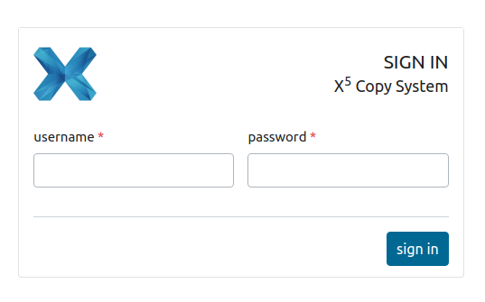
Figure 1: Login mask
With a click on the "user button" in the upper right corner, a drop down menu opens. By clicking on the link ![]() the user is immediately logged out of the X⁵ System. There won't be an additional demand. The login form is displayed afterwards.
the user is immediately logged out of the X⁵ System. There won't be an additional demand. The login form is displayed afterwards.

Figure 2: Menu bar with sign out link in the user drop down menu
Change password
Logged-in user can change their password with click on the "user button" on the upper right. By selecting in the drop down menu, an input form to change the password is displayed.

Figure 3: Menu bar with change password link in the user drop down menu
To change the password, the old password, a new password and the confirmation of the new password have to be entered. A password must contain at least 8 characters and can't be entirely numeric. After clicking on ![]() the new passwort is verificated and - if successfull - saved.
the new passwort is verificated and - if successfull - saved.
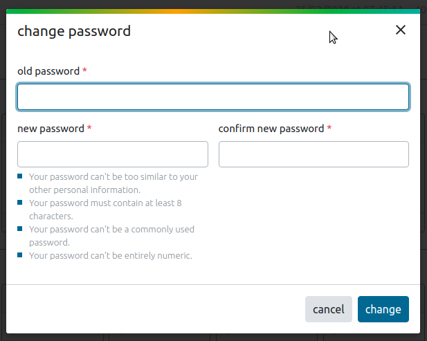
Figure 4: Change password form
Forgot your Password?
If a user has forgotten his/her password, there are two ways to regain access to the software:
- If no mail server was given for the X⁵ in the system control settings (see chapter email settings), the user must contact the administrator for a password reset. The administrator then can set the new password in the user management for the respective user (see more details in chapter User management).
- If a mail server was given for the X⁵ in the system control settings a link,
 is displayed at the bottom of the login mask (see chapter email settings). This allows user to reset their password themselves.
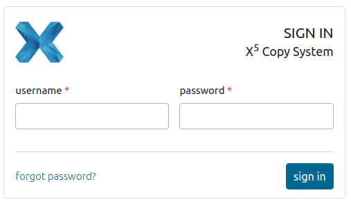
Figure 5: Login mask with "forgot password" link
After clicking on the link "forgot password", the standard procedure to reset a password starts. A new window opens to enter the user email address. By clicking on ![]() the request to set a new password is started.
the request to set a new password is started.
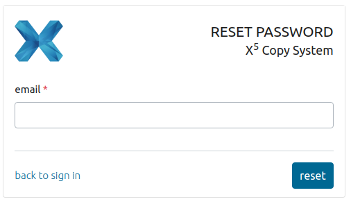
Figure 6: email input form for resetting the password
A message appears - We've emailed you instructions for setting your password. If you don't receive an email, please make sure you've entered the address you registered with and check your spam folder.
This email contains a link. By clicking on it, the user is redirected to the "change password form" to set the new password. To finish this process the user has to click on ![]() and the new password is saved after a successful check.
and the new password is saved after a successful check.
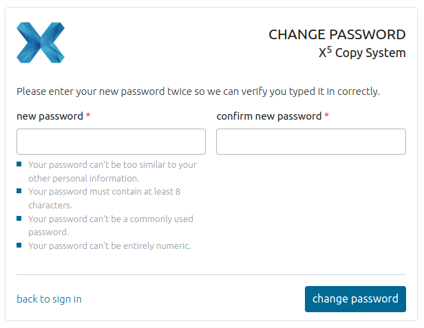
Figure 7: new password input form for resetting the password
First Steps to Start Operation
1. On and off switch
2. Socket for USB connection of X⁵
3. Socket for power connection of X⁵
4. Socket for network connection of X⁵
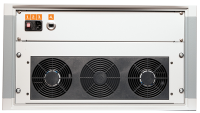
Figure 8: Backside of the X⁵ with marked sockets
Following steps are necessary to set up the X⁵ and make it ready for operations:
1. Connect the power cable to the X⁵ (socket number 3 in figure 8)
2. To set up the label printer, the power cable has to be plugged into the printer and a connection must be established between the printer and the X⁵ using the USB cable (socket 2 of the figure 8).
3. Connect the X⁵ to the network (socket 4 in figure 8)
4. Turn on the modules via the purple power button on the front side of the individual modules (marked with the orange circle in figure 9 beside)
5. The network configuration is either already preconfigured by X-Net or happens by default via DHCP.
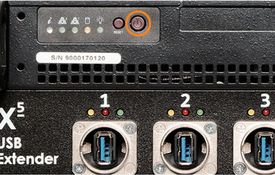
Figure 9: Front side of an X⁵ module with marked button to switch on
6. After successful set up the module's lights turn green (see figure 10). The X⁵ is ready for use.

Figure 10: X⁵ module with USB ports and status lights above
Once the monitor has started, the default standard administrator is asked to reset the password (see figure 11 beside) in order to gain access to the software.
The default password (old password") is admin.
After the new password has been set, the administrator can log in.
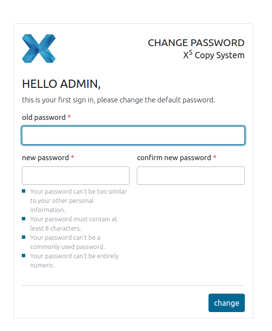
Figure 11: First form after starting the system.
The administrator is first shown an empty start page (see chapter Status page). Now the user can start using the software and create new tickets for copy jobs, as described in detail in the following chapter.
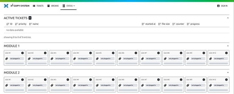
Figure 12: Emtpy status page as start page
Standard WorKflow
A standard workflow for copying data to a respective device is structured as follows:
- Create a new ticket and select data for the copy process
- Start the ticket- this is followed by the preparation of data, which are copied from the master to the system. After successful copying process, the workflow waits until a device is plugged into the selected and reserved X⁵ slot.
- Preparing data - Data will be copied from the master to the service
- Plug in the device into the reserved slot
- Actual copy process starts
- Unplug the device from the slot - if specified in the ticket, a label will be printed afterwards
The structure of the standard workflow mentioned above is very simplified. The following chapters give a detailed explanation of these functions.
1. Create new Ticket
The first step of the standard workflow is to create a new ticket. There are two ways to create a new ticket, as indicated in the figure 13:
- via the menu item
 or
or - opening the ticket list with the menu item
 and click on the plus icon
  in the table header of the ticket.
When clicking on one of these two possibilities, a window opens and contains a wizard that guides through the creation process.

Figure 13: Two possibilities to start a ticket
In the following subchapters, the wizard is explained step by step and possible setting variants are illustrated:
Step 1: General
First the ticket name and the number of copies have to be defined. The ticket name can be set individually.
Continue with the ![]() button
button

Figure 14: Step 1 - General information of the ticket
Step 2: Device
This step varies depending on how many devices (SSD, SD, USB etc.) can be recorded with the respective X⁵ system. The number of the selected devices determines the number of device tabs in the wizard (see more in subchapter Multiple Devices).
For this documentation, the creation of a ticket is only explained in detail with one USB device. As seen in figure 15, the wizard contains only one device tab, which represents the USB medium.
To set the device configurations select the type of the source in the drop down menu first. The data source can be a folder or an image.
Depending on which type of source is selected, the area on the right of the window changes:
If the folder option is chosen, a certain directory must be selected (see figure 15 on the left).
The verify device controller can be used for control purposes to specify the percentage of files which are read in again after writing on the device. The setting of the verification is not mandatory.
Go on with the ![]() button.
button.
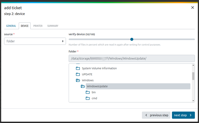
Figure 15: Step 2 - Device specifications with folder as source
If the image option is selected as source, a certain image in a directory must be selected in the displayed structure or an image can be uploaded with the specified file formats (.bin, .img, .iso, .raw).
After choosing an image, go on with the ![]() button.
button.
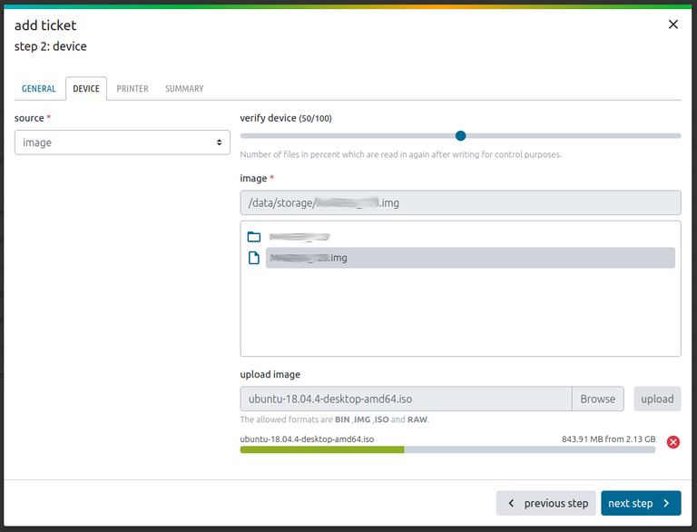
Figure 16: Step 2 - Device specifications with image as source
Multiple Devices
If multiple devices for recording are available (like USB, SSD and SD), a separate tab will appear for each device (see figure 17). In each tab the device type can be selected in the drop down menu device #. The tab device 1 is mandatory.
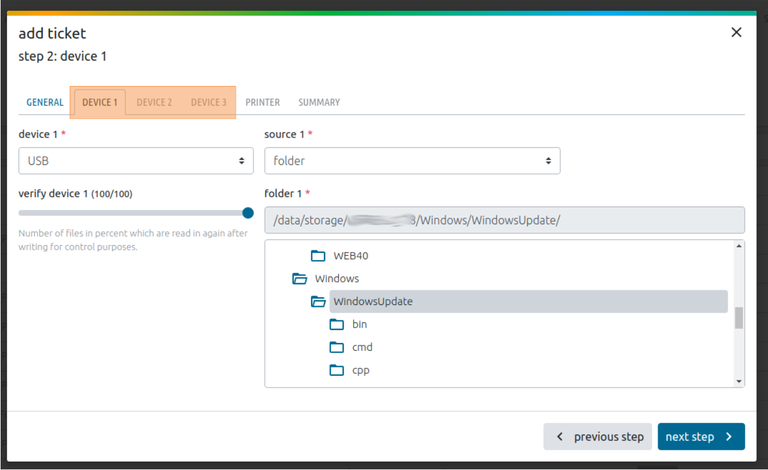
Figure 17: Extraordinary step with multiple devices
Multiple devices can be available for two reasons:
- Your modules use different port types (e.g. 5 ports for USB and 5 ports for mSD).
In this case, only the first tab 'device 1' is compulsory. Select the desired device type and the source for device 1. The other tabs are optional and do not have to be entered if they are not needed. This is also the case when only one device type is used. - You use multi adapters (e.g. a SATA adapter which connects SSD and mSD)
In this case, a user has to fill out all the device tabs. The system automatically recognizes the multi adapters and matches them with the correct ticket.
Step 3: Printer
If desired, a label can be printed for the device after recording and after the device has been removed. The tab "printer" is not mandatory. There are two ways to set the text for the label:
- via text input or
- via file
When a text input is selected in the drop down menu of source, a text field appears on the left side of the window. In this field any text can be entered.
Continue with the ![]() button.
button.
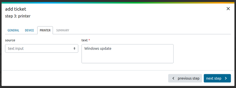
Figure 18: Step 3 - printer specifications with text input
Alternatively a file can either be selected from the file system or an external file can be uploaded for the device label with the specified file format (.pdf).
Continue with the ![]() button.
button.
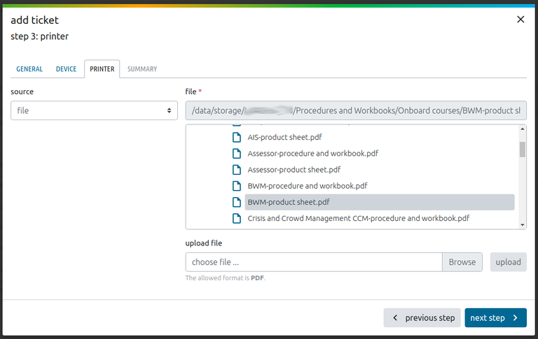
Figure 19: Step 3 - printer specifications with file
Step 4: Summary
When the last register tab "summary" is reached an overview of the set parameters is clearly displayed.
If corrections or adjustments of the data are necessary, it is possible either to go back the tabs step by step with the ![]() button or to click on the tabs for the desired step.
button or to click on the tabs for the desired step.
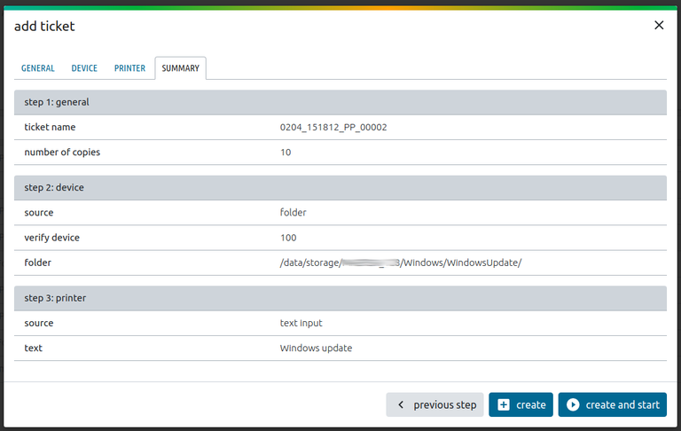
Figure 20: Summary of the created ticket
To complete the add ticket process, two different buttons can be pressed to create the ticket in the list:
![]() creates and starts the ticket at once, a new window opens (see subchapter 2. Start Ticket). Afterwards it is visible in the ticket list.
creates and starts the ticket at once, a new window opens (see subchapter 2. Start Ticket). Afterwards it is visible in the ticket list.
![]()
creates the ticket and inserts it in the ticket list, however waits until it is started (see figure 21).
2. Start ticket
After the ticket has been successfully created, it will be listed in the ticket list. In case the ![]() button has been clicked, it does not start automatically. The ticket must be started manually by clicking on
button has been clicked, it does not start automatically. The ticket must be started manually by clicking on ![]() . The ticket only starts automatically when creating the ticket with the
. The ticket only starts automatically when creating the ticket with the ![]() button.
button.
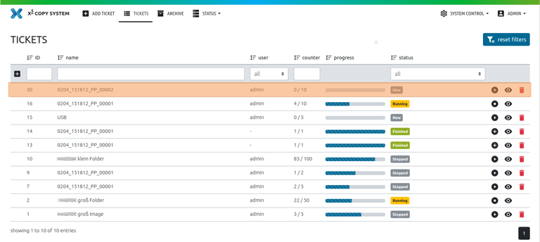
Figure 21: Ticket was successfully added in the ticket list
After either clicking on ![]() or
or ![]() , a new window opens where slots can be reserved for recording the devices by selecting them. It is possible to reserve a slot on which a job is currently still running. When this is finished, the selected slot is reserved for the new ticket. If a slot is already reserved, like #slot 10 in module 2 (see figure 22), it is not possible to reserve this slot a second time for another ticket.
, a new window opens where slots can be reserved for recording the devices by selecting them. It is possible to reserve a slot on which a job is currently still running. When this is finished, the selected slot is reserved for the new ticket. If a slot is already reserved, like #slot 10 in module 2 (see figure 22), it is not possible to reserve this slot a second time for another ticket.
Once the reservation is completed, the ticket can finally be started with the ![]() button.
button.
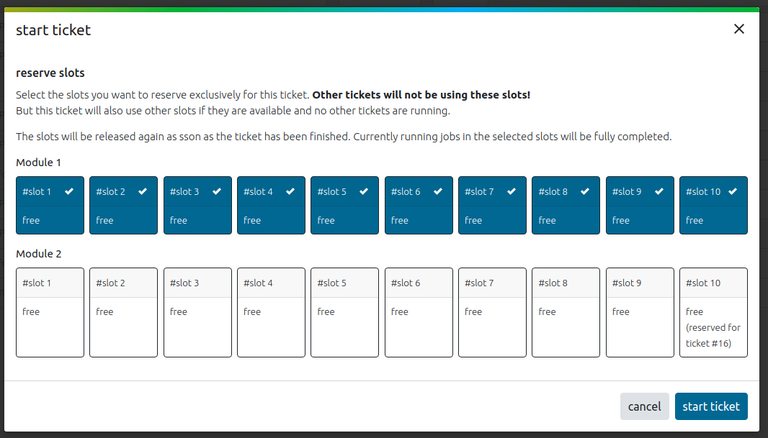
Figure 22: Module to reserve slots
After the ticket has been started it immediately goes into the wait status for a short time. During this time, the ticket prepares the data for the copy process.
Note: If the allowed maximum number of running tickets has already been reached and another ticket has started, it remains on "hold"/ and then automatically switches to preparing/running status as soon as one of the running tickets is finished. and then automatically switches to preparing/running status as soon as one of the running tickets is finished. |

Figure 23: Ticket has 'waiting' status
3. Preparing data
When the waiting process is finished, the data is prepared for recording on the device in the background.
To make this process visible for the user, the ticket status in the ticket list changes into .
.

Figure 24: ticket has 'preparing' status
To make this process even more tangible, it is now graphically visualized step by step in the following table:
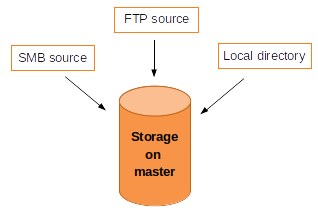
1. Copy data to masterThe data is copied to the master from multiple sources. These sources can be:
|
Figure 25: Master storage and multiple sources |
2. Label generationThe label is generated. This only happens if a label print has been configured during ticket creation. |
|
3. Calculation of checksumsIf verification is activated, MD5 sums are calculated for every file and stored in the master database. From this point on the status of prepared is "True". The status prepared remains "True" until the ticket data is automatically deleted after completion (see general settings "clean up sections"). |
|
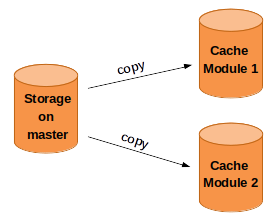
4. Copy files to modulesAll files, including the label PDF, are copied into the cache of each module. From this point on the status of cached is "True". The status cached remains "True" until the cache space is needed by another ticket. If a ticket is finished and no other ticket has been started yet, it remains in the cache. For this purpose see in the general settings maximum cached tickets, which defines how many tickets are kept in the cache. When a new ticket is added, the oldest ticket is always thrown out. |
Figure 27: Distribution of data from master to modules |
5. RunningWhen all these steps are successfully done, the preparation of data is completed and the devices can be plugged into the defined slots. |
|
|
Note: When the lamps are red or flashing red, the port is NOT READY to be plugged in. This means that either a faulty device from the previous order is still plugged in and the slot is just initializing itself OR the software is not (yet) running.
Figure 28: Red flashing lights on the module |
4. Plug in device
The next step is to plug in the devices into the USB ports. Only green lamps above the USB ports indicate that a device may be plugged in.
| Note: In general, a device may be plugged in when a ticket is running, before or after starting a ticket, but only when it is green. |

Figure 29: Green lights on the module
When it is plugged in, it is checked if the device is recognized. It takes about half a second and the lamps are flashing yellow. Meanwhile the device is being initialized - reading out the vendor, model, size and serial number. When the initialization process is completed, the lamps are yellow and the device is ready for recording. Only then the device will be displayed in the web interface.
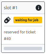
Figure 30: Ticket has 'waiting' status

Figure 31: Yellow flashing lights on the module
5. Record device
Figure 32: Ticket has 'writing' status
When the actual recording process begins, the yellow and red lamps above the USB ports are flashing.

Figure 33: Yellow and red lights on the module
After all files have been copied on the devices, the slot goes to the next status - verification. As mentioned above, when creating a ticket it is possible to specify the percentage of data that will be checked again. This check happens right after the data is copied on the device.
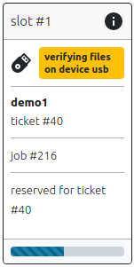
Figure 34: Ticket has 'verification' status
At the end, depending if the copying process was successful, different lights appear on each slot:
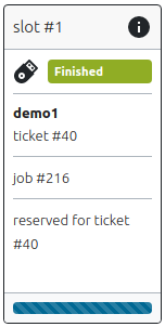
Figure 35: Ticket has 'finished' status
turn green flashing ⮞ copy progress was successful, go the next step 6. unplug device

Figure 36: Green flashing lights on the module
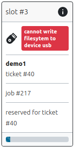
Figure 37: Ticket has 'error' status
turn red flashing ⮞ the copy progress raised an error. To find out more about this error check the specific slot with the error message in the graphical interface. To correct the error, record the device again in a different slot. If an error also occurs there, the device is probably faulty. But if always the same slot with different devices and tickets throws an error, then the slot itself may be faulty.

Figure 38: Red flashing lights on the module
6. Unplug device
The device can now be removed from the port. If the ticket parameters specify that a label is printed, this will happen after unplugging the device. To enable printing, the printer must be connected to the X⁵ and switched on (see more in chapter Printer). After unplugging the device and printing the labell the job of this ticket is finished and the slot light turns green again for the next job.

Figure 39: Green lights on the module
Status
The status view is always visible when starting the software (touch screen) or after the login. This page is also accessible in the menu bar by clicking on the menu item![]() or the X⁵ logo
or the X⁵ logo ![]()
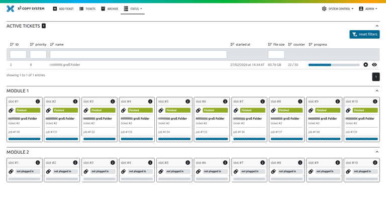
Figure 40: status overview page
The status page is structured as follows:
- active tickets (standard)
- at least one module (standard)
as shown in the picture above. Each X⁵ can optionally have more than one modules, which are shown one below the other in the UI.
Each section can be folded in ![]() or out
or out ![]() with the arrows on the right side of the section.
with the arrows on the right side of the section.
1. Active Tickets Section
This table shows all currently running tickets and gives information on their status. Actions can be performed, e.g. stop tickets or show details. Filtering functions help to search for specific tickets or states. The number of active tickets is displayed with the number field ![]() next to the headline.
next to the headline.
All available actions and information for this section are explained below:
![]() by clicking on this icon the running ticket is stopped.
by clicking on this icon the running ticket is stopped.
![]() by clicking on this icon the ticket details are displayed.
by clicking on this icon the ticket details are displayed.
![]() the progress bar shows the current status of the processed copies of the ticket.
the progress bar shows the current status of the processed copies of the ticket.
 by clicking on this icon, the columns of the table are being sorted.
![]() this button resets all set filters in the input fields of the column headers
this button resets all set filters in the input fields of the column headers

Figure 41: section of the active tickets in the status overview page
2. Selected Module
When clicking on the menu item ![]() a drop down menu opens. All modules (default for the standard home page) or only a specific module to be displayed can be selected here. In the drop down menu (marked orange in figure 42) module 1 or module 2 can be selected for the specific modules. Figure 42 shows that module 1 has been selected.
a drop down menu opens. All modules (default for the standard home page) or only a specific module to be displayed can be selected here. In the drop down menu (marked orange in figure 42) module 1 or module 2 can be selected for the specific modules. Figure 42 shows that module 1 has been selected.
When one of the specific modules is clicked (e.g. module 1 in figure 42), a new section 'Jobs' appears under the table of active tickets. The job section contains the same information as the slot blocks in the module section but the information is displayed in table form. In the table it is possible to stop a running job with ![]() .
.
| Note: One ticket consists of several jobs. The number of jobs results from the amount of defined copies in the ticket. So the table 'Jobs' contains all the active jobs of the running ticket. After the job is finished and the device is unplugged from the X⁵ slot, the entry disappears from the job table. |
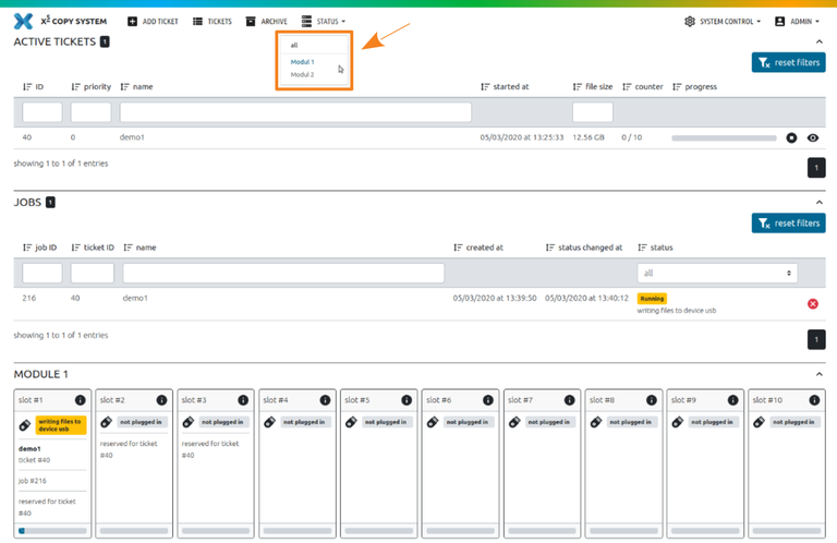
Figure 42: section of running jobs in the status page of the specific module
3. slot detail
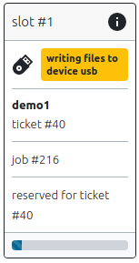
One module section is divided into ten slot blocks. Each slot consists of the following information:

⮞ name and #number/id of the slot - with a click on ![]() icon or the whole slot, the ticket and slot information will be displayed in a separate window.
icon or the whole slot, the ticket and slot information will be displayed in a separate window.
⮞ device type (e.g. USB) and current status of the running job in this slot
⮞ ticket name and ticket #number/id
⮞ job #number/id (unique id for this job)
⮞ reservation information for a slot based on the ticket #number/id - this area is optional, and is only filled out when a slot has been reserved before
⮞ current process progress of the running job in this slot
Figure 43: slot detail view
4. Mobile View
In the mobile view the status information is displayed compactly and summarized per section, table and slot. The individual sections can be folded in and out with the arrows on the far left![]() to show more information. Depending on the status of the individual slots in the modules a summarized icon is displayed in the header of the module:
to show more information. Depending on the status of the individual slots in the modules a summarized icon is displayed in the header of the module:
 when all slots were successful
![]() when one of the slots raised an error
when one of the slots raised an error
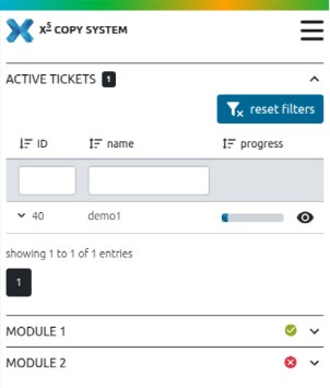
Figure 44: Mobile view of the status overview
Ticket list
Show ticket list
The tab ![]() contains an overview of all recently created or edited tickets.
contains an overview of all recently created or edited tickets.
The tickets remain in the list until they are automatically deleted from the database, as set in the settings. Finished and faulty tickets are handled separatly, see chapter General Settings.
As soon as a ticket is finished, it will also be displayed in the archive list, see more in chapter Archive.
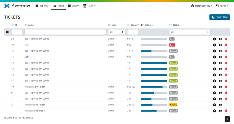
Figure 45: Status ticket list view
The columns can be individually sorted by clicking this icon ![]() and filtered with the input field in the header of the columns. With the
and filtered with the input field in the header of the columns. With the ![]() button the set filters can be reset.
button the set filters can be reset.
The table is divided into the following columns:
- ID of the ticket
- Name of the ticket
- User, who created the ticket
- Counter: defines how many copies of the total number have already been processed
- Progress bar shows the progress graphically
- Status varies according to the workflow process
- Icons for performing various actions
The various action options change depending on the status of the ticket:
| Status | Actions | Description of the action | Next Status after action |
 |
Starts the processing of the ticket |  |
|
| Continues the processing of the ticket |  |
||
| Retries the processing (after fixing the error) |  |
||
 |
 |
Stops the ticket | |
 |
Stops preparing of the ticket | ||
 |
Stops the processing of the ticket, jobs/devices currently in production will be finished | ||
 |
 |
Copies the ticket data into a new one and creates a new ticket with a new amount of copies in the list. |
|
In addition to the start, stop and edit actions, other operations can be performed:
1. Show details of a ticket
If the user clicks on the ![]() icon, a detailed overview of the ticket properties is displayed.
icon, a detailed overview of the ticket properties is displayed.
On the left side the information of the whole ticket is listed:
- Name of the ticket
- Quantity (describes the number of copies)
- Finished (defines the number of jobs that were already successfully processed)
- User, who created the ticket
- Priority (determines the order in which the tickets are processed. If the priority of two tickets is equal, the start date decides the order of the processed tickets.)
- Status (defines the current state of the ticket)
- Created at (the date when the user created the ticket)
- Started at (the date when the user started the recording process of the ticket)
- Prepared (describes whether the data was successfully loaded into the system or not)
- Cached describes if this ticket is still cached on the modules
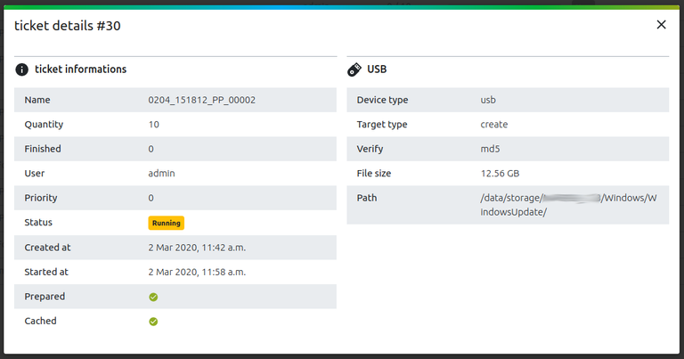
Figure 46: Mobile view of the status overview
On the right side the ticket target information is displayed (in this case each job records only one USB device):
- Device type
- Target type describes how the medium is recorded. This can happen in two ways and can be selected when a ticket is created:
- create (like in figure 46) - a file system is created and the files are copied on the device.
- image - an image is written bit by bit to the medium
- Verify defines if the device is verified after the copy process. This property can have two different values:
- no - when no verification is set in the ticket
- md5 - describes the checksum format. This checksum is used for the verification, which can be set with a controller in creating a ticket. First the checksum will be created of the USB and the source and subsequently will be checked for equality.
- File size describes the storage capacity of the device
- Path describes the exact source of the data to be recorded
2. Delete a ticket
If the user clicks on the![]() icon, the corresponding ticket is going to be deleted from the list.
icon, the corresponding ticket is going to be deleted from the list.
Only tickets with the status ![]() ,
, ![]() ,
,  or
or ![]() can be deleted.
can be deleted.
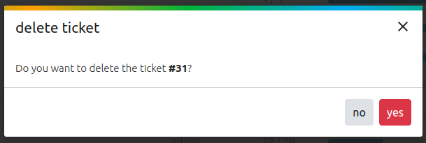
Figure 47: Confirmation message to delete a ticket
![]() if no copy process has been started yet, the ticket and the corresponding database entries will be deleted immediately.
if no copy process has been started yet, the ticket and the corresponding database entries will be deleted immediately.
Ticket with the status ![]() ,
, or
or ![]() have already started the copying process. These tickets cannot be deleted, they are only hidden from the ticket list. The actual deletion process including the database entries happens after the time set in the general settings. The finished tickets settings affect the finished tickets and the faulty tickets settings affect the error and stopped tickets.
have already started the copying process. These tickets cannot be deleted, they are only hidden from the ticket list. The actual deletion process including the database entries happens after the time set in the general settings. The finished tickets settings affect the finished tickets and the faulty tickets settings affect the error and stopped tickets.
| Note: If a ticket with a different status wants to be deleted, the user has to wait until the ticket changes into one of the four states mentioned above. |
Archive
As soon as a job is finished, it will be displayed in the archive list. This list serves mainly for the traceability of individual recording processes. See a detailed view of each job in the table by pressing the ![]() icon.
icon.
Depending on the defined parameters in general settings, the entries will be deleted from the database after a while.
The archive list contains all jobs that have already been processed. The list is divided into the following columns:
- job ID (number of the single job in a ticket)
- ticket ID (number of a ticket)
- name (the title of the ticket)
- completed (date when the ticket was finished successfully)
- user who created the ticket
- serial number (of the USB device, which is read out during initialization)
- icons for performing various actions:
 the respective details can be displayed for tickets (grey background) or for jobs.
 for each job of a ticket, the label can be printed even after the job has been completed for some time.
 Each ticket can be folded or unfolded to hide unused information in the table.
Each column can be sorted by  or filtered with the respective input field in the header of the column. The set filters can be deleted with
 ![]() .
.
The whole table can be filtered with the "from" and "to" date at the top of the table. After entering the dates, the table is automatically updated with the entered data. The default date is today (to) and goes back to the 1st of the last month (from).
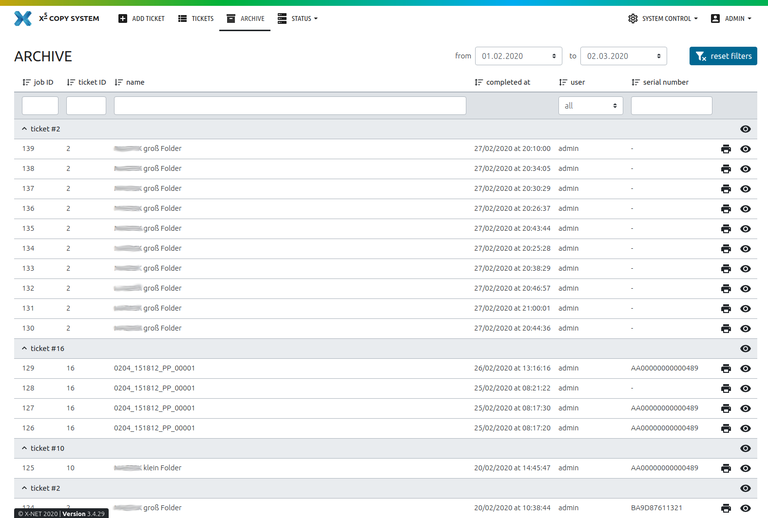
Figure 48: Archived tickets overview page
Configuration
The administrator is the only user role who has the right to perform the system control. The system control can be found in the menu bar to the left of the users name.
Clicking on it opens a drop down menu with individual functions:

Figure 49: Menu bar contains system control drop down for user administrator
1. User management
The list in the user management contains all registered users - administrators or standard users.

Figure 50: User list
In the header of the users table the user has the possibility to add a new user. A click on the icon  opens a window with a form. The minimum requirements to add a new user are the username and password.
By activating the checkbox admin, the user gets all permission without explicity assigning them.
By activating the checkbox active, the user is able to log into the software. Instead of deleting the user laster, uncheck this checkbox.
With the ![]() button the user is saved with the specified properties and appears in the user table.
button the user is saved with the specified properties and appears in the user table.
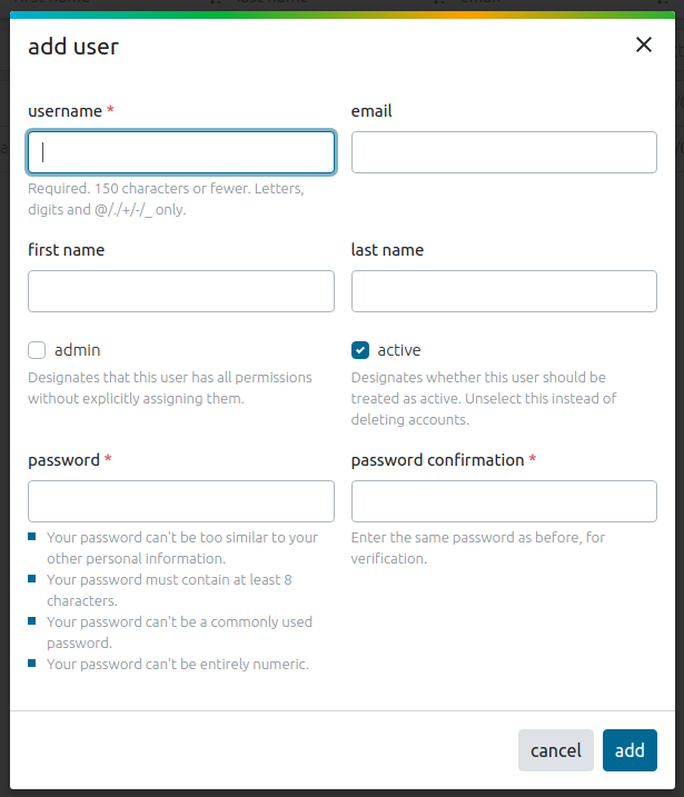
Figure 51: Form to add a new user
The user lists each entry can be edited with the following actionsFor each user following actions, which are located on the far right of each line:
 by clicking on this icon, a new window opens. In this the user properties can be changed. The admin checkbox defines, if the respective user has all permissions for this software. The active checkbox defines, whether the respective user has login rights for the software.
With the ![]() button the data is saved.
button the data is saved.
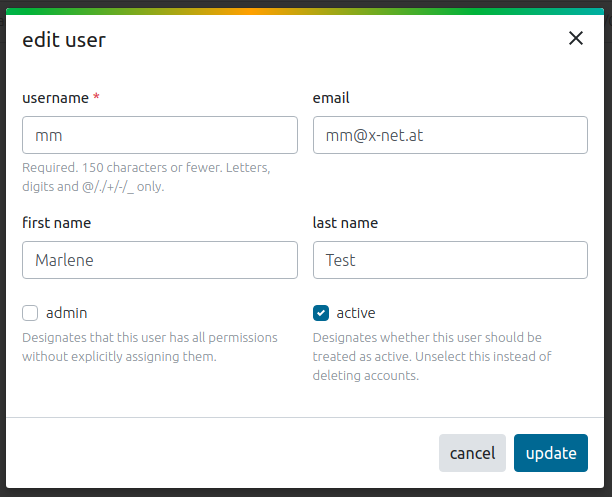
Figure 52: Edit user form
 by clicking on this icon, the administrator can edit the password for a specific user or reset the own password. For this, the administrator has to enter a new password with the corresponding specifications as listed in the form.
With the ![]() button the data is saved.
button the data is saved.
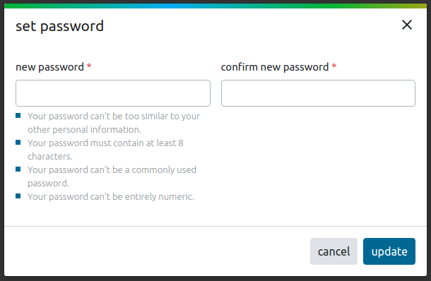
Figure 53: Reset password form
 deletes the respective user from of the system. To be sure, a window with an additional question opens. The administrator can delete all users except himself.
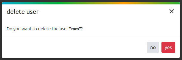
Figure 54: Confirmation question to delete an user
2. Settings
The settings in the system control are divided into four different sections:
- In the general settings it is possible to set configurations concerning the tickets and the clean up after recording.
- In the email settings the mail configurations can be set.
- In the printer settings it is possible to set a printer to print the labels for the recorded devices.
- In the privacy settings can be specified if data is allowed to be sent to X-Net for analytical purposes.
By clicking at one of the four icons the individual configurations can be set.
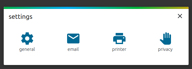
Figure 55: Four setting sections
1. General Settings
First the language can be set to either German or English. When a language is selected, the system must be restarted to activate the language (See chapter Restart Service ).
The maximum number of running and cached tickets can be set. This configuration is for adjusting and optimizing the system utilization and the average order size.
When the ticket is finished, it can be specified after how many days a ticket is deleted from the database. Also floating point numbers like e.g. 3,5 days (3 days and 12 hours) can be entered.
When the ticket occurs an error, it can be specified after how many days this ticket is deleted from the database and the system.
With ![]() the entered configurations are saved.
the entered configurations are saved.
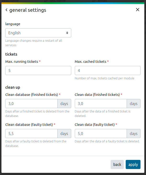
Figure 56: General settings form
2. Email Settings
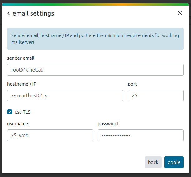
In the email settings form it is possible to configure the mail server for the system.
This settings are necessary to activate the ![]() link in the login mask.
link in the login mask.
With ![]() the entered configurations are saved.
the entered configurations are saved.
Figure 57: Email settings form
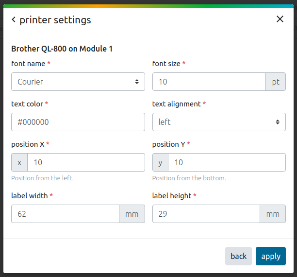
3. Printer Settings
The printer settings (see figure 58) are necessary for the labels, which are printed automatically (when set in the ticket configurations) after a ticket is finished successfully.
All positions are given in millimetres.
This settings only apply to tickets created using the web interface ticket wizard. Tickets created using external tools or plugins use the sizes and positions specified in the json.
With ![]() the entered configurations are saved.
the entered configurations are saved.
Figure 58: Printer settings form
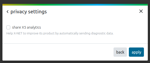
4. Privacy Settings
With the checkbox "share X5 analytics" it is possible to specify, whether data is sent to X-Net for analytical purposes. No user or input data is stored. It is only used for the analysis of errors, which occurred in the user interface. For this to work, a mail server must be configured (see more in chapter email settings).
With ![]() the entered configurations are saved.
the entered configurations are saved.
Figure 59: Privacy settings form
3. Shutdown system
The whole system can be shut down in the system control drop down in the menu bar.
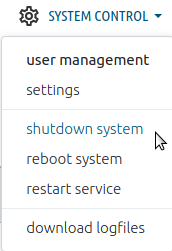
Figure 60: Shutdown system link in system control management
After pressing the link "shutdown system" a new window opens:
The default setting "all" turns the whole system off. But it is also possible to select the master or the individual modules with the drop down menu to turn them off separately. By clicking ![]() the shut down process starts and the modules go into the offline mode.
the shut down process starts and the modules go into the offline mode.
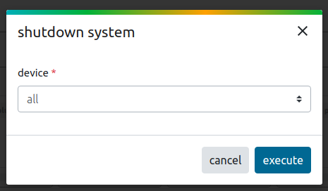
Figure 61: Shut down system form
4. Reboot system
The whole system can be rebooted in the system control drop down in the menu bar.
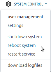
Figure 62: Reboot system link in system control management
After pressing the link "reboot system" a new window opens:
The default setting "all" reboots the whole system. But it is also possible to select the master or the individual modules with the drop down menu to reboot them separately. By clicking ![]() the reboot process starts. Then the system or one of the selected modules is offline for a short time.
the reboot process starts. Then the system or one of the selected modules is offline for a short time.
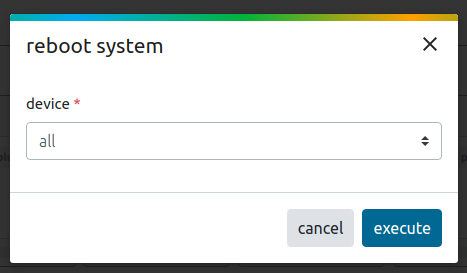
Figure 63: Reboot system form
5. restart service
The whole service can be restarted in the system control drop down in the menu bar.
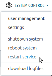
Figure 64: Restart service link in system control management
After pressing the link "restart service" a new window opens:
The default setting "all" restarts the whole service. But it is also possible to select the master or the individual modules with the drop down menu to restart them separately. By clicking ![]() the restart process starts. Then the system or one of the selected modules is offline for a short time.
the restart process starts. Then the system or one of the selected modules is offline for a short time.
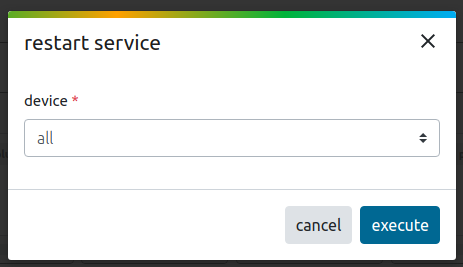
Figure 65: Restart service form
6. Download logfiles
To download the log files for debugging or problem analysis, only one click on the link in the system control drop down menu is necessary. The download will start automatically and can be extracted afterwards in the file system.
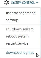
Figure 66: Download logfiles link in system control management
Possible error handling
Modules are offline
When a module is offline, this can have several reasons:
- it is switched off
- it is not plugged in
- the software does not run on the system
- any network problems (check cable connections)
If one of these cases occurs, the user will be informed accordingly visually in the web interface.
When only an individual module is offline, it is marked red - like the module 2 in figure 67.

Figure 67: Module shows an offline status
When the whole service or the master is unavailable, an animation (as shown in figure 68) occurs on the screen. The user has to wait until the notification disappears.
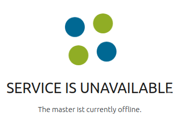
Figure 68: the web interface shows an unavailability of the system
Inhaltspezifische Aktionen


